Abstract
Today’s electrical power system is a complicated network that is expanding rapidly. The power transmission lines are more heavily loaded than ever before, which causes a host of problems like increased power losses, unstable voltage, and line overloads. Real and reactive power can be optimized by placing energy resources at appropriate locations. Congested networks benefit from this to reduce losses and enhance voltage profiles. Hence, the optimal power flow problem (OPF) is crucial for power system planning. As a result, electricity system operators can meet electricity demands efficiently and ensure the reliability of the power systems. The classical OPF problem ignores network emissions when dealing with thermal generators with limited fuel. Renewable energy sources are becoming more popular due to their sustainability, abundance, and environmental benefits. This paper examines modified IEEE-30 bus and IEEE-118 bus systems as case studies. Integrating renewable energy sources into the grid can negatively affect its performance without adequate planning. In this study, control variables were optimized to minimize fuel cost, real power losses, emission cost, and voltage deviation. It also met operating constraints, with and without renewable energy. This solution can be further enhanced by the placement of distributed generators (DGs). A modified Artificial Hummingbird Algorithm (mAHA) is presented here as an innovative and improved optimizer. In mAHA, local escape operator (LEO) and opposition-based learning (OBL) are integrated into the basic Artificial Hummingbird Algorithm (AHA). An improved version of AHA, mAHA, seeks to improve search efficiency and overcome limitations. With the CEC’2020 test suite, the mAHA has been compared to several other meta-heuristics for addressing global optimization challenges. To test the algorithm’s feasibility, standard and modified test systems were used to solve the OPF problem. To assess the effectiveness of mAHA, the results were compared to those of seven other global optimization algorithms. According to simulation results, the proposed algorithm minimized the cost function and provided convergent solutions.
Introduction
The optimal power flow (OPF) minimizes generation costs, power losses, and voltage stability while adhering to system restrictions1. OPF is a large-scale, nonlinear, constrained, nonconvex optimization problem in power systems. This problem has been addressed with linear programming, nonlinear programming, quadratic programming, Newton, and interior point methods. These traditional methods, however, have certain limitations and require specific theoretical assumptions. Consequently, they are limited in their optimization abilities2,3,4. Despite this, solving the OPF problem remains a popular and challenging task.
Researchers have recently discovered that metaheuristic algorithms, which are all-purpose and straightforward to use, can tackle challenging real-world problems. Because metaheuristics are very accurate and straightforward, they have drawn much attention in various challenging optimization issues in engineering, communications, medical, and social sciences5. Moreover, metaheuristic algorithms are also used to improve solutions for a variety of problems, such as global optimization6, energy applications7, power flow systems8, image segmentation9, 10, deep learning-based classification11, economic emission dispatch (EED) problems12, and feature selection13, 14. In contrast to deterministic algorithms, metaheuristic algorithms employ specialized operators and randomly generated search agents to find optimal solutions. Natural phenomena, such as swarms and social behavior, evolutionary principles, and physical theories, inspire these operators. In general, metaheuristic algorithms fall into three categories: swarm methods, which simulate animals, birds, and humans’ social behavior; evolutionary methods; and natural phenomena algorithms15.
Metaheuristic methods have gained popularity in solving complex OPF problems using population-based techniques. Researchers have studied these methods with only thermal power generators16. The traditional OPF issue was solved by Kumari17 using an upgraded genetic algorithm (GA), and Khunkitti18 utilized a hybrid dragonfly and PSO technique for minimizing fuel loss, emissions, and power loss. Based on FACTS devices, Basu19 proposed a DE method that considers generating costs, emissions, and power losses to overcome OPF issues. Singh20 overcomes IEEE-30 and IEEE-118 OPF problems using PSO and an aging leader and challenger. An adapted Sine–Cosine algorithm with Levy flights was used in Attia’s21 solution to the OPF problem.
It is apparent from the literature that traditional OPF issues only consider thermal power sources. Since fuel prices have increased and environmental concerns have been heightened, a stochastic OPF has been necessary to optimize renewable energy sources22, 23. However, wind energy has been incorporated in a variety of ways, such as the use of genetic algorithms by Liu24, the use of a fuzzy selection mechanism by Hetzer26, and the use of hybrid flower pollination by Dubey27. In addition, other studies have considered the stochastic nature of wind power and the variable nature of its loads. As examples, Miguel examined the impact on operating costs25, Kusakana included solar photovoltaic, wind, diesel generators, and batteries28, and Partha used a historical parameter adaptation approach to combine wind and solar power30.
Furthermore, the Gray Wolf Optimizer method was applied to the IEEE-30 bus and IEEE-57 bus systems to combine thermal power, wind energy, and solar energy31. In addition, Arsalan used the Krill Herd algorithm to solve OPF problems relating to wind energy generation under uncertainty in both the IEEE-30 bus system and the IEEE-57 bus system32. In modified IEEE 30-bus and IEEE 57-bus systems33, Mohd applied the Barnacles Mating Optimizer method to the OPF problem with stochastic wind energy. Shuijia Li34 presented a penalty constraint handling strategy for solving OPF in an IEEE-30 bus system utilizing an enhanced adaptive DE. However, an overview of soft computing contributions to OPF literature can be found in Table 1.
Although these algorithms were aimed at solving the same OPF issues, their optimization functions were different, which led to various optimized solutions resulting in different optimization performance that is assessed by the quality of the optimum solution and the convergence time. Even though many metaheuristic methodologies have shown satisfactory outcomes, optimization problems have become more challenging due to the increasing number of variables and constraints that can be optimized. However, metaheuristic optimization algorithms cannot always obtain the optimal global solution, regardless of their advantages. Further, no algorithm is suitable for solving all variants of the OPF problem due to the variability of objectives used to formulate it. It is, therefore, necessary to develop metaheuristic algorithms capable of handling various OPF formulations very effectively. In order to address current optimization challenges, combining two or more metaheuristics and modifying or improving existing algorithms is necessary. This procedure is known as hybridization51.
Nevertheless, selecting hybridization algorithms that will enhance optimization performance is essential. Thus, choosing an algorithm is an important step in the process, typically based on its performance. It is therefore recommended to study more recent algorithms and features to develop a more effective algorithm for solving OPF problems. Particularly, the artificial hummingbird algorithm (AHA) has attracted great interest. Despite the promising results achieved by the AHA method, this method is not entirely impervious to metaheuristic flaws. Several studies have pointed out the algorithm’s slow convergence speed and tendency to get trapped in local optima. They also discuss the significant effect algorithm parameters have on algorithm performance and the inadequacy of exploration and exploitation. Hence, this paper suggests a modified artificial hummingbird algorithm (mAHA) that addresses these limitations by integrating the local escape operator (LEO) and opposition-based learning (OBL) into the basic AHA.
In this paper, we introduce a novel and enhanced approach to address the challenges in solving the Optimal Power Flow (OPF) problem. While various metaheuristic algorithms have shown promise in tackling OPF problems, they often face limitations, such as slow convergence speed and susceptibility to local optima. This paper presents a significant contribution in the form of the modified Artificial Hummingbird Algorithm (mAHA), which effectively addresses these limitations by integrating the local escape operator (LEO) and opposition-based learning (OBL) into the basic AHA. The key objective of this paper is to combine OPF with Renewable Energy Sources (RESs) to optimize scheduled power from RESs and generating power from thermal units, thereby minimizing the total operational cost. To validate the effectiveness of our proposed approach, we apply the mAHA algorithm to standard IEEE 30, and 118 bus systems for solving traditional OPF issues, as well as a modified IEEE-30 bus system that incorporates RES. Our contributions include developing and testing the mAHA algorithm on a range of benchmark functions, comparing it with established metaheuristic algorithms, and demonstrating its efficacy in integrating RES into the OPF problem. These contributions collectively provide a comprehensive and innovative solution to enhance the optimization of power systems. The main contributions of this work can be summarized in the following items:
-
This paper proposed a modified mAHA algorithm and tested through unimodal, multimodal, and composite benchmark functions .
-
The performance of mAHA compared to competitors is demonstrated using the CEC’2020 benchmark test problems.
-
Present four different objective functions for formulating the real-world problem called OPF problem.
-
mAHA converts the multi-objective function, which includes fuel costs, power losses, voltage deviations, and emissions, into a single-objective function based on price and weighting factors.
-
Several benchmark problems from the metaheuristic literature are tested, including IEEE 30, and 118 bus grids, to assess the effectiveness and scalability of the proposed algorithm.
-
A comparison is made between the performance of mAHA and various established meta-heuristic algorithms to verify its validity and effectiveness, including the Whale optimization algorithm (WOA), Sine cosine algorithm (SCA), Tunicate swarm algorithm (TSA), Slime mould algorithm (SMA), Harris hawks optimization (HHO), RUNge Kutta optimization algorithm (RUN), and the original Artificial Hummingbird Algorithm (AHA).
-
Efficient Integration of renewable energy sources (RES) and external electric grid (EEG) has been suggested to overcome the OPF problem.
-
The mAHA technique is applied to a modified version of the IEEE 30-bus grid that includes the optimum allocation of RES via the OPF issue. This test demonstrates the superiority of the suggested methodology over other state-of-the-art metaheuristic techniques.
After the introduction section, the presented paper is constructed in the following sections: Section “Preliminaries” provides the mathematical model for the basic AHA algorithm required to construct the proposed modified algorithm, the OBL strategy, and the Local Escaping Operator (LEO). Section “The proposed mAHA algorithm” provides the mathematical model of the proposed mAHA algorithm. Section “Application of mAHA: optimal power flow and generation capacity” introduces the OPF mathematical formulation model. Section “Evaluated results and discussion” discusses the design findings. The discussion contains the performance results of the proposed mAHA on CEC’2020 benchmark functions. It also contains the results of the proposed mAHA based on the OPF problem. Section “Conclusion” presents this paper’s conclusion and future work.
Preliminaries
This section will cover the fundamental methods needed to construct the proposed method. We will comprehensively explain the mathematical model of the Artificial Hummingbird Algorithm (AHA), the OBL approach, and the local escaping operator (LEO) technique.
Artificial hummingbird algorithm (AHA)
Based on the behavior of hummingbirds, the AHA technique was developed to solve real-world problems52. The hummingbird is an incredible creature among the smallest birds in the world. By replicating the axial, diagonal, and omnidirectional flight techniques of hummingbirds, the AHA algorithm seeks to replicate the flight abilities and intelligent foraging strategies of these birds. Foraging strategies, memory capacity, and flight abilities of hummingbirds have been incorporated into the algorithm. Furthermore, the AHA algorithm incorporates guided foraging, territorial foraging, and migrating foraging techniques. Tracking food sources mimics hummingbird memory by using a visiting table. As a result of the AHA algorithm, the following three main elements are explained:
-
Food sources: When selecting food sources, hummingbirds consider factors such as the quality and content of nectar in individual flowers, the rate at which nectar is refilled, and the last time they visit the flowers. In the AHA algorithm, each food source is assumed to have the same type and quantity of flowers, represented by a solution vector. Its fitness value indicates the nectar-refilling rate. A food source with a higher nectar-refilling rate will have higher fitness.
-
Hummingbirds: Every hummingbird is given a unique food source to feed from, and the bird and the food source are positioned in a specific location. A hummingbird can remember the exact location of the food source and the frequency of nectar replenishment for that particular source. This information can be communicated to other hummingbirds in the population. Moreover, each hummingbird can recall its last visit to a particular food source.
-
Visit table: A table is maintained to record the visit history of different hummingbirds to each food source, indicating the duration since a particular bird last fed from it. When a hummingbird decides to feed, it prioritizes a food source with a high visit level for that specific bird. If multiple food sources have the same highest visit level, the bird selects the one with the highest nectar-refilling rate to obtain more nectar. This visit table helps each hummingbird to locate its preferred food source. Typically, the visit table is updated after each feeding loop.
AHA mathematical model
The three mathematical representations simulating three foraging behaviors of hummingbirds: guided foraging, territorial foraging, and migrating foraging are presented as follows:
Step 1: Initialization
A population of N hummingbirds is established on N food sources, randomly initialized as Eq. (1)
where (Xb_{i}) denotes the solution in a population set of N. (lb_{i}) and (ub_{i}) are the lower and upper boundaries, respectively.
The visit table of food sources is initialized in Eq. (2)
Step 2: Guided foraging
To exhibit guided foraging behavior, the hummingbird must identify food sources with the highest visit level and choose the one with the most rapid nectar replenishment as its target. Once identified, the bird can navigate toward the desired food source. The AHA algorithm incorporates three flight skills to direct the search space during foraging: omnidirectional, diagonal, and axial flights. The axial flight is described by Eq. (3).
The diagonal flight is calculated by Eq. (4)
The omnidirectional flight is calculated by Eq. (5)
where (randi([1,d])) obtains an integer random from 1 to d, (randperm(l)) generates a random permutation of integers from 1 to l, and (r1) is a random number between [0, 1].
Using different flying patterns, Eq. (6) simulates directed foraging behavior by allowing each food source to update its location relative to the target food source. It also depicts the foraging activity of hummingbirds.
Where (Xb_{i} (t)) denotes the (i^{{{text{th}}}}) position, (Xb_{i,targ} (t)) denotes the position of the target food source, and a denotes the guided vector.
The updating positions are applied using Eq. (8).
where (f(.)) denotes the objective function. Equation (8) illustrates that if the candidate food source’s nectar-refilling rate is greater than the current one, the hummingbird discards the current food source and remains at the candidate food source calculated using Eq. (6) for feeding.
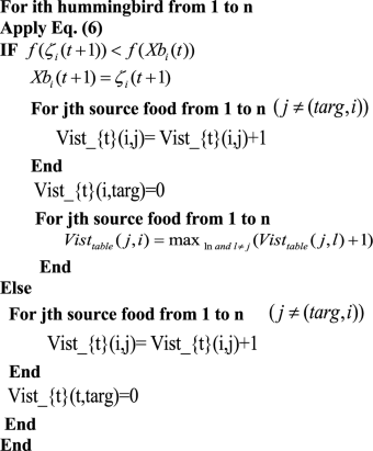
The visit table records the time elapsed since a specific hummingbird last visited each food source, and a more extended period between visits indicates a higher visit level. Each hummingbird seeks the food source(s) that receives the most visitors. If two or more sources have an equal number of visits, the bird chooses the one with the highest rate of nectar replenishment as its target food source. Each bird navigates to its intended food source using Eq. (6). When a hummingbird uses Eq. (6) to guide its foraging during each iteration, the visit levels of other food sources visited by that specific bird are increased by 1. In contrast, the visit level of the target food source visited is set to 0. A hummingbird can engage in guided foraging with a guide to reach its preferred food source, then remain at the new food source until a better nectar-refilling rate (solution) or food quality (deterioration) becomes available.
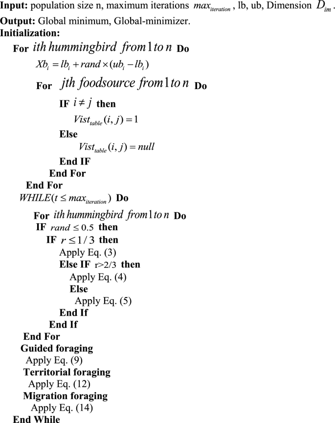
The following schema illustrates AHA’s guided foraging method:
Step 3: Territorial foraging
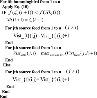
During this step, a hummingbird can migrate to a nearby location within its territory, where it may find a new food source that could be a better solution than the current one. The local search of hummingbirds in the territorial foraging strategy is modeled using Eq. (10), which helps to identify a candidate food source by:
Where b is a geographic variable, the visit table has to be updated following the territorial foraging approach. The following diagram illustrates AHA’s territorial foraging strategy:
Step 4: Migration foraging
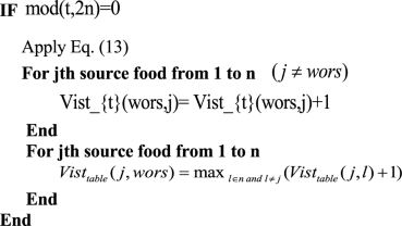
The hummingbird at the food source with the lowest rate of nectar replenishment will randomly move to a new food source established in the whole search space once the number of iterations exceeds the predefined value of the migration coefficient. A hummingbird’s foraging trip from the source with the lowest nectar replenishment rate can be modeled using Eq. (13).
where (X_{wors}) denotes the food source with the worst nectar-refilling rate. Equation (14) illustrates the migrating foraging strategy of AHA.
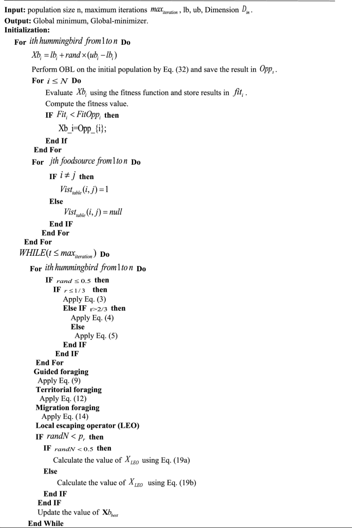
A visiting table and a set of random solutions are created to summarize the AHA algorithm’s process. Each iteration has a 50% probability of carrying out territorial or guided foraging. Hummingbirds use guided foraging to travel to the food sources they prefer, which are determined by the frequency of their visits and the rate at which the nectar is replenished. However, due to territorial foraging, hummingbirds are forced to disturb their local populations. They are foraging while migration begins after 2n iterations. Three flight abilities—omnidirectional, diagonal, and axial—are used in the three foraging tasks. All operations are carried out interactively until the stopping criteria are met. The pseudo-code for the AHA procedure is provided in Algorithm 1.
Opposition-based learning (OBL)
The OBL technique is an efficient method for avoiding stagnation in potential solutions. HR developed it. Tizhoosh53 to enhance the search mechanism’s exploitation ability. When using meta-heuristic algorithms, convergence usually happens quickly when initial solutions are close to the optimal position, but slower convergence is expected otherwise. However, the OBL technique can discover more valuable solutions in opposite search regions that may be closer to the global optimum. To achieve this, the OBL searches in both directions of the search space. One of the initial solutions is used for both directions, while the opposite solution represents the other. The OBL then selects the most appropriate solutions from all solutions found.
Opposition number: The concept of opposite numbers represents opposition-based learning. An opposition-based number can be described as follows. Lets consider (Q_{0}) it a real number on an interval: (Q_{0} in [a,b]) the opposite number (Q_{0}) is defined by Eq. (15).
Equations (16) and (17) identify the opposite point in D-dimensional space.
The items in (overline{{text{Q}}}) are computed by Eq. (18)
Opposition-based optimization: In the optimization strategy, the opposite value (overline{Q}_{0}) is replaced by the corresponding (Q_{0}) based on the objective function. If (Q_{0}) is more suitable (f(overline{Q}_{0} )), then (Q_{0}) not changed; otherwise, the solutions of the population are updated based on the best value of (Q) and (overline{Q}_{0})54.
Local escaping operator (LEO)
The LEO is a technique proposed in55 that is utilized to enhance the effectiveness of the Gradient-based optimizer (GBO) algorithm in resolving complex real-world issues. Its purpose is to explore new areas necessary for finding solutions to challenging problems. By changing the position of solutions based on specific criteria, LEO improves the quality of the solutions and prevents the algorithm from being trapped in local optima. LEO selects new solutions ((X_{LEO}^{H})) by utilizing various techniques, such as the best position ((Xb_{best})), two randomly chosen solutions (X1_{r1}^{m}) and (X2_{r2}^{m}), two other randomly selected solutions ((Xb_{r1}^{m}) and (Xb_{r2}^{m})), and a newly generated random solution ((X_{k}^{m})). Thus, the solution (X^{H}_{LEO}) can be obtained using the following:
where, (f_{1}) and (f_{2}) are uniformly distributed random values in [-1, 1], (P_{r}) denotes a probability number equal to 0.5. (u1), (u2), and (u3) are random numbers obtained from the following equations:
where (randN) is a random value between zero and one. (mu_{1}) is between 0 and 1. We can simplify the equations of (u1), (u2), and (u3) in the following mathematical representation:
where (L_{1}) is a parameter with a value of 0 or 1. (L1 = 1 if (mu_{1} < 0.5), and 0 otherwise).
The following scheme is presented to obtain the solution in Eq. (19).
where (x_{{text{randN }}}) is a new solution that can be calculated as shown in Eq. (27), (x_{p}^{m}) is a random solution selected from the population ((p in [1,2, ldots N])), (mu_{2}) is a random number in the range of [0,1].
Moreover, (rho_{1}) is used to balance the exploration and exploitation phases. It is defined by:
where (beta_{min }) and (beta_{max }) are equal to 0.2 and 1.2, respectively, t is the current step and (t_{max}) is the highest number of steps—changes according to the sine function to balance the exploration and exploitation phases (alpha).
Equation (26) can be simplified using Eq. (31):
where (w_{2}) is a parameter with a value of 0 or 1. If the parameter (mu_{1}) is less than 0.5, the value of L1 is 1; otherwise, it is 0.
The proposed mAHA algorithm
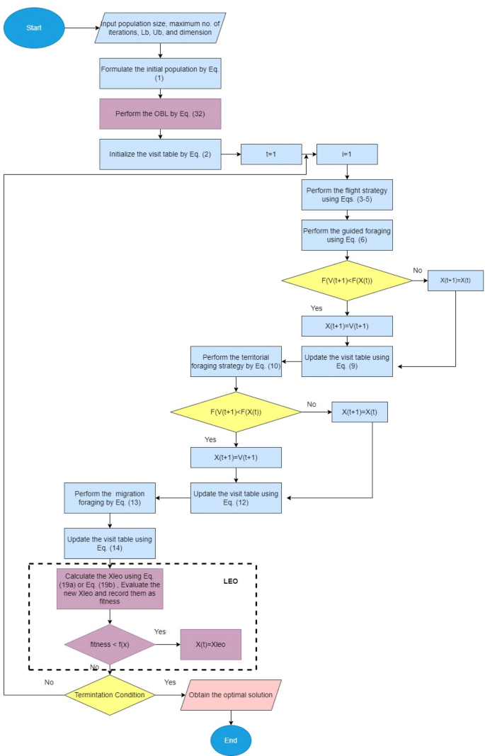
In this section, we present a detailed explanation of the proposed mAHA optimization algorithm, which aims to improve the searchability of the AHA and eliminate its weaknesses in solving complex real-world problems. The mAHA algorithm consists of two effective schemes: the LEO and the OBL. To enhance the performance of the original AHA, the OBL strategy is utilized in the initialization phase. After that, the steps of the original AHA are carried out as usual, and the LEO is used to improve its performance further.
Drawbacks of the basic AHA algorithm
The basic AHA algorithm is based on hummingbirds’ foraging behavior, including guided foraging, territorial foraging, and migrating foraging. The algorithm generates diverse solutions by randomly applying these foraging strategies. However, in some optimization issues, the AHA algorithm can get trapped in sub-regions, resulting in improper exploration–exploitation balance, particularly in complex and high-dimensional problems. Since each solution updates its position based on the previous one, the algorithm’s convergence rate is reduced, and it cannot effectively cover search space solutions, leading to premature convergence. Therefore, we have developed a new version of the AHA algorithm to address these limitations. The LEO prevents getting trapped in sub-regions, solving premature convergence by updating solutions using a robust strategy and randomly selecting a solution over the search space. Furthermore, we utilize the OBL to improve the algorithm’s search efficiency, considering the No Free Lunch (NFL) theory that no superior optimization algorithm works well for all optimization problems.
Initialization of the proposed mAHA
The initialization process of the mAHA algorithm follows the AHA algorithm and starts by proposing an initial population of (N) search agents. Each search agent is limited by upper and lower boundaries (uba and lba) in the search space, as described in Eq. (1). The mAHA algorithm aims to enhance the diversity of the search process, which is achieved through the utilization of the OBL strategy during the initialization phase. This helps to improve the search operation, as demonstrated in Eq. (32).
where (Opp_{s}) is a vector produced by applying OBL. (lb_{a}), and (ub_{a}) are lower and upper bounds of the (a^{th}) component of Y, respectively. After that, the visit table of food sources is initialized, as shown in Eq. (2).
Fitness evaluation of the proposed mAHA
It is compulsory to assess the solutions in each iteration to estimate the proposed solutions and to improve the new proposed solutions in the next step. In each iteration, the population of hummingbird positions is evaluated to get the fitness value of each solution (f(x)). The best solution is determined (Xb_{best}) and is used in updating the position rule.
Updating process of the proposed mAHA
The AHA update steps are divided into two processes, as described in Eq. (33). The first process is divided into three steps, as illustrated in subsection “AHA mathematical model“; guided foraging, territorial foraging, and migration foraging. There is a probability of 50% to perform either guided foraging or territorial foraging. In the guided foraging, each search agent is updated using equations presented in Eqs. (6)–(9). While in the territorial foraging phase. The search agents are updated using equations presented in Eqs. (10)–(12). The migration foraging is applied every 2n iteration as illustrated in Eqs. (13) and (14). The second process works on the received solutions from previous process and target to significantly change these solutions using the LEO operator (described in details in subsection “Local escaping operator (LEO)“). Depending on specific criteria ((randN < p_{r})), the final process is applied. Where (randN) is a random value between zero and one, and (P_{r}) is a probability value for performing the second process.
Termination criteria of the proposed mAHA
The proposed mAHA optimization process is repeated until the stopping criteria is met. The pseudo-code of the proposed mAHA algorithm is provided in Algorithm 2 and the flowchart is presented in Fig. 1.
Application of mAHA: optimal power flow and generation capacity
Formulizing OPF mathematically
Optimizing the power system’s control variables allows the objective function of the OPF issue can be maximized to meet specific objectives. To achieve this, different equality constraints and inequality constraints must be satisfied at the same time. This optimization problem can be put into mathematical terms by explaining it in the following way:
Conditional on:
where function F is the representation of the objective function. The vector (x) contains the dependent variables (state variables), while the vector (u) contains the independent variables (control variables). Additionally, ({g}_{j}) and ({h}_{j}) respectively represent the equality and inequality requirements. The variables (m) and (p) indicate the number of equality and inequality constraints.
The following are the state variables ((x)) in a power system:
where the power of the slack bus is denoted by ({P}_{G1}), and ({V}_{L}) denotes the load bus voltage, the reactive output power for the generator is denoted by ({Q}_{G}), the apparent power flow of the transmission line is denoted by ({S}_{TL}), the number of load buses is denoted by (NPQ), the number of generation buses is denoted by (NG), and (NTL) in the power system denotes the number of transmission lines.
In a power system, the control variables ((u)) are as follows:
where the generator output power is indicated by ({P}_{G}), generation bus voltage is indicated by ({V}_{G}), injected shunt compensator reactive power is indicated by ({Q}_{C}), transformer tap settings are indicated by (T), (NT) indicates transformers and shunt compensator units are indicated by (NC). It is important to note that these variables are relevant in this context.
Objective functions
It is necessary to define an objective function to select the optimal solution. Several objectives are evaluated in the OPF, considering constraints within the system. In addition, the OPF determines the system’s optimal control variables and objectives. Techno-economic advantages are associated with the most efficient OPF solution. These are sometimes called OPF objectives. As a result of these objectives, fuel costs will be reduced, resulting in a reduction in annual operating costs as well as technological benefits, such as3: Minimization of active power losses, Minimization of reactive power losses, Improvement in system reliability and power quality; Deviation of voltage; and stabilization of voltage.
Single objective functions
The objective function described above is one of the most frequently used objective functions within the field of statistics, and it can be performed as follows56:
Basic fuel costs minimization objective
The primary goal of the OPF problem is to minimize the total fuel costs, which is achieved through an objective function. For each generator, the objective function can be expressed as a quadratic polynomial function, given by:
where, ({F}_{i}) is the (i) th generator fuel cost. ({a}_{i}), ({b}_{i}), and ({c}_{i}) are the cost coefficients for (i)th generator.
Generation emission minimization objective
It is beneficial to decrease the quantity of gas released by thermal power plants to decrease pollution. The goal for regulating gas emissions can be described as follows:
where, ({gamma }_{i}), ({beta }_{i}), ({alpha }_{i}),({upzeta }_{i}), and ({lambda }_{i}) are the (i) th generator’s emission coefficients.
Active power losses minimization objective
The intended goal is to reduce the actual power loss, and this can be expressed in the following manner:
where, ({G}_{ij}) is the transmission conductance, NTL is the transmission lines number, and ({delta }_{ij}) is the voltages phase difference.
Voltage deviation
Using this objective function, minimizing the deviation of voltages on the load nodes from a predetermined voltage is possible. The following formula can describe this:
Multi-objective functions
When dealing with a multi-objective issue, the main aim is to optimize various objectives that are independent of each other, and this is defined in the following equation:
where (i) is the number of the objective function, the optimization with the weighting factors as follows can be used to solve multi-objective functions:
where ({w}_{11}), ({w}_{2}) and ({w}_{3}) are weight factors chosen based on the relative importance of one goal to another. Suitable weighting factors are selected by the user. In this paper, the values of the weight factors are chosen for each case as mentioned below:
|
Case no. |
Description |
Objective function |
Wight factors |
Network |
Control variable no |
|---|---|---|---|---|---|
|
1 |
Minimization of fuel cost |
({F}_{1}=sum_{i=1}^{NPV}({a}_{i}+{b}_{i}{P}_{Gi}+{c}_{i}{{P}^{2}}_{Gi})) |
– |
Standard IEEE 30 & 118 bus |
24/128 |
|
2 |
Minimization of active power losses |
({F}_{3}=sum_{i=1}^{NTL}{G}_{ij}({{V}^{2}}_{i}+{{V}^{2}}_{j}-2 {V}_{i}{V}_{j}mathrm{cos}{delta }_{ij})) |
– |
Standard IEEE 30 & 118 bus |
24/128 |
|
3 |
Minimization of total voltage deviation |
({F}_{4}=sum_{i=1}^{NPQ}left|{V}_{i}-1right|) |
– |
Standard IEEE 30 & 118 bus |
24/128 |
|
4 |
Minimization of fuel cost and power losses |
({F}_{i}left(x,uright)={F}_{1}+{w}_{1}{F}_{3}) |
({w}_{1}=20) |
Standard IEEE 30 |
24 |
|
5 |
Minimization of fuel cost and total voltage deviation |
({F}_{i}left(x,uright)={F}_{1}+{w}_{1}{F}_{4}) |
({w}_{1}=200) |
Standard IEEE 30 |
24 |
|
6 |
Minimization of fuel cost and power loss with emission |
({F}_{i}left(x,uright)={F}_{1}+{w}_{1}{F}_{2}+{w}_{2}{F}_{3}) |
({w}_{1}=0.0021, {w}_{2}=20) |
Standard IEEE 30 |
24 |
|
7 |
Minimization of multi-objective function (voltage-level deviation, operational cost, and transmission power loss) without emission |
({F}_{i}left(x,uright)={F}_{1}+{w}_{1}{F}_{3}+{w}_{2}{F}_{4}) |
({w}_{1}=200, {w}_{2}=100) |
Standard IEEE 30 & 118 bus |
24/128 |
|
8 |
Minimization of multi-objective function (voltage-level deviation, operational cost, and transmission power loss) with emission |
({F}_{i}left(x,uright)={F}_{1}+{w}_{1}{F}_{2}+{w}_{2}{F}_{3}+{w}_{3}{F}_{4}) |
({w}_{1}=0.0065, {w}_{2}=200, {w}_{3}=100) |
Standard IEEE 30 |
24 |
|
9 |
Optimal allocation for renewable energy sources for minimizing fuel cost |
({F}_{1}=sum_{i=1}^{NPV}({a}_{i}+{b}_{i}{P}_{Gi}+{c}_{i}{{P}^{2}}_{Gi})) |
– |
Standard IEEE 30 |
3 |
|
10 |
Minimization of the fuel cost with the penetration of RES |
({F}_{1}=sum_{i=1}^{NPV}({a}_{i}+{b}_{i}{P}_{Gi}+{c}_{i}{{P}^{2}}_{Gi})) |
– |
Modfied IEEE 30 |
24 |
|
11 |
Minimization of the fuel cost simultaneously with the penetration of RES |
({F}_{1}=sum_{i=1}^{NPV}({a}_{i}+{b}_{i}{P}_{Gi}+{c}_{i}{{P}^{2}}_{Gi})) |
– |
Standard IEEE 30 |
27 |
System constraints
There are already many constraints in the system that can be classified as follows:
The equality constraints
The equality constraints for the balanced load flow equations are as follows:
where ({P}_{Gi}) and ({Q}_{Gi}) are the active power and reactive power generated respectively at bus (i). The active and reactive demand of the load at bus (i) are represented by ({P}_{Di}) and ({Q}_{Di}), respectively.({G}_{ij}) and ({B}_{ij}) represent conductance and susceptibility among buses (i) and (j), respectively.
Inequality constraints
The classification of inequality constraints is as follows:
The incorporation of dependent control variables can be achieved seamlessly in an optimization solution by utilizing the quadratic penalty formulation of the objective function. In this paper, the optimization problem can be rewritten based on the penalty functions as follows:
where ({K}_{G}), ({K}_{Q}), ({K}_{V}), and ({K}_{S}) are penalty factors with large positive values, also (Delta {P}_{G1}), (Delta {Q}_{Gi}), (Delta {V}_{Li}), and (Delta {S}_{Li}) are penalty conditions that can be stated as follows:
Evaluated results and discussion
This section describes two experiments to assess mAHA performance using different metrics. The first experiment used mAHA on 10 problems taken from the CEC2020 benchmark functions57, while the second experiment focused on testing mAHA’s effectiveness in solving the OPF problem. The OPF problem was tested on the IEEE 30-bus system.
Experimental Series 1: global optimization with CEC’2020 test-suite
Several benchmark function challenges presented by the CEC’2020 illustrate how well the mAHA performs. Several well-known metaheuristic methodologies are compared with this mAHA technique to evaluate its effectiveness: the WOA58, the SCA59, the TSA60, the SMA61, the HHO, the RUN63, and the basic AHA algorithm52.
Definition of CEC’20 benchmark functions
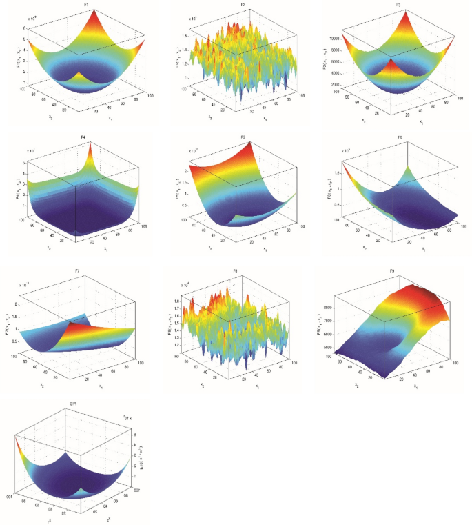
In order to evaluate the proposed method’s performance, IEEE CEC’2020 benchmarks64 were used as test problems to estimate its performance. As part of the benchmarking process, 10 different test functions have been included to cover uni-modal, multi-modal, hybrid, and composition test functions. Here are the benchmark test characteristics and mathematical equations, with ‘Fi*’ denoting the optimal global value. Figure 2, three-dimensional views of CEC’2020 functions (Table 2).
Parameter settings
To compare the mAHA algorithm and other algorithms, 30 runs were conducted. All considered problems had a fixed number of function evaluations (Fes) set at 30,000. Table 3 displays the parameter settings for each algorithm, as reported in the original literature. Qualitative and quantitative metrics were utilized to evaluate the algorithms’ effectiveness.
Performance criteria
The proposed algorithm’s efficiency in finding the best solutions is evaluated against comparison algorithms using a collection of performance metrics in this paper. The definitions for these metrics are outlined below:
Statistical mean: This metric determines the fitness value that is situated in the center, and it is computed using the following equation:
The worst value: This metric is utilized to compute the highest fitness value that the algorithm can achieve, and it is defined as:
The best value: This metric computes the minimum fitness value, and it can be defined as follows:
Standard deviation (STD): The STD is calculated by the following equation:
where (R_{n}) represents the total number of runs.
Statistical investigation on CEC’2020 test-suite
The proposed mAHA algorithm is compared to WOA, SCA, TSA, SMA, HHO, RUN, and AHA on the CEC’2020 test suite, and statistical results are obtained. A measure of the algorithm’s performance is assessed by calculating the mean value and standard deviation of the best-so-far solutions obtained within each run. Based on the dimension ‘Dim = 10’ of the CEC’2020 test suite, Table 4 displays mean, standard deviation, best, and worst values. Boldfaced values highlight the most appropriate values.
As shown in Table 4, the results show that the mAHA technique reaches the optimum value with respect to the single-modal benchmark function F1 for the unimodal model. There is no doubt that mAHA has an advantage over the algorithms which are compared for multi-modal functions F2, F3, and F4 in terms of performance. Nevertheless, regarding the F4 function, the most accurate values can be obtained using mAHA, AHA, RUN, and SMA. In addition, the proposed mAHA technique performs better than any of the other methodologies regarding the hybrid F5, F6, and F7 test functions. For the composite functions F8, F9, and F10, the mAHA algorithm outperforms the other algorithms. The mAHA and AHA algorithms provide optimal F8 values. For test function F9, optimal results are achieved by the mAHA and SMA algorithms. In contrast, for the F10 test function, the mAHA, AHA, RUN, and SMA techniques achieve optimal values.
In terms of resolving the CEC’2020 benchmark functions, the statistical results indicate that the mAHA methodology performs better than any of the other methods. A comparison of the mean, the standard deviation, the best value, and the worst value can be made to reveal this. It is also noteworthy that, in the Friedman mean rank-sum test, the proposed mAHA algorithm achieved the top ranking in the Friedman algorithm test.
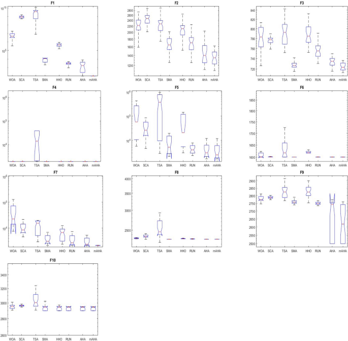
Boxplot behavior analysis
Boxplots are a valuable and effective tool for analyzing data visually and representing its empirical distribution. They are created by dividing the data into quartiles, with the highest and lowest whiskers representing the maximum and minimum values in the dataset. The box represents the lower and upper quartiles, providing insight into the data’s spread and level of agreement. When the box is narrow, it indicates a high degree of symmetry in the data.
Figure 3 shows the boxplot distribution for the CEC’20 test functions from F1 to F10 with a dimension of 10. The results of the introduced mAHA algorithm demonstrate narrower boxplots and minimum values compared to other algorithms for most test methods. These graphical results confirm the mAHA algorithm’s consistency in finding optimal regions for the test problems.
Evaluation of convergence performance
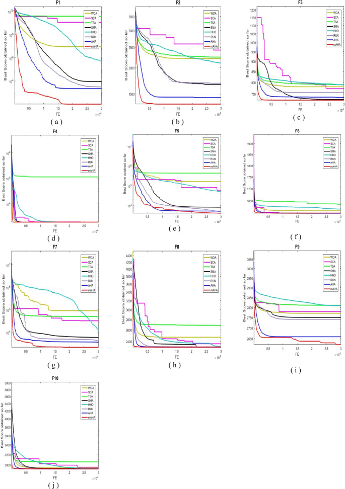
Algorithm convergence is discussed in this subsection. For CEC 2020 test problems for dimension 10, Fig. 3 compares WOA, SCA, TSA, SMA, HHO, RUN, and AHA to the developed mAHA. Figure 4a shows that the F1 function with a unimodal space exhibits convergence curves. It has been demonstrated that the proposed mAHA is superior to the original AHA and all other algorithms compared. It is evident in Fig. 3b–d that the developed mAHA algorithm displays a greater level of exploration than the standard OPA algorithm and the other algorithms that have been compared on the benchmark functions of F2–F4. Using the benchmark F5 function, the proposed mAHA and the original AHA have significant results, as illustrated in Fig. 3e–g. A significant performance improvement was also achieved by the mAHA for functions F6 and F7. Therefore, the mAHA is more effective at handling hybrid functions. It was demonstrated from the composition functions (F8, F9, and F10) in Figs. 3h–j that the proposed mAHA was able to solve problems involving complex spaces with comparable performance.
Experimental series 2: applying mAHA for solving OPF problems
On the IEEE 30-bus test grid, the effectiveness of the mAHA methodology is evaluated to address the OPF issue. This section compares simulation results between those obtained by mAHA and those obtained by recent metaheuristic algorithms to solve OPF. An evaluation of mAHA’s ability to minimize fuel costs, active power loss, total voltage deviation, and emissions is conducted for one-objective and multi-objective problems considering weight factors. Using the presented cases, it is possible to determine these weight factors.
mAHA’s effectiveness is further demonstrated by comparing it to other algorithms. The test is conducted on a modified IEEE 30-bus grid to determine its effectiveness in optimizing RES allocation and minimizing fuel costs. Experimental tests are used to determine which parameters are appropriate for mAHA and other methods. Each algorithm is run 30 times on the test system with different parameters. A MATLAB 2021b platform is used to apply mAHA and other comparing techniques to solve the OPF issue. This is accomplished by using a PC with a 2.8GHz I7-8700 CPU and 16 GB of RAM.
IEEE 30-bus grid
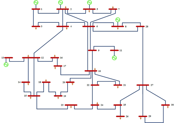
IEEE 30-bus grid has six generation power units, 41 lines, and 24 load buses66. Figure 5 shows node number 1 is a slack bus66. In terms of active power and reactive power, the total connected load has 2.834 pu of active and 1.262 pu of reactive power, respectively. A voltage magnitude of 0.95 Pu and 1.1 Pu is limited for the power-generating nodes, while a voltage magnitude of 0.95 Pu and 1.05 Pu is limited for the remaining load nodes. VAR compensator limits fluctuate between 0 and 0.05 pu, and tap-changing transformers can be adjusted between 0.9 and 1.1 pu.
Case 1: minimization of fuel cost
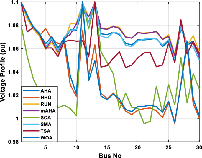
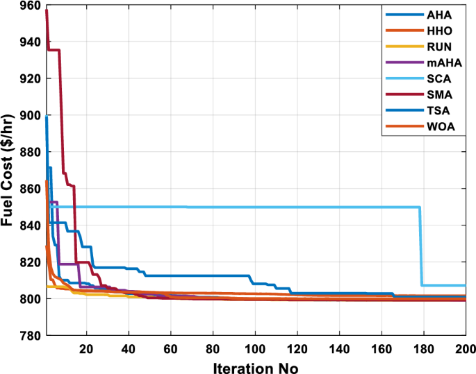
A mAHA methodology is proposed for reducing fuel costs using only the IEEE 30-bus grid. According to Table 5, mAHA achieves optimal outcomes as opposed to other literature techniques, such as AHA, HHO, RUN, SCA, SMA, TSA, and WOA. The mAHA technique produces the lowest fuel cost of 799.135 $/h, outperforming other methodologies. The mAHA’s voltage profile is also displayed in Fig. 6, ensuring that all nodes’ voltages are within acceptable limits. As can be seen in Fig. 7, the convergence characteristics of the standard algorithm and other compared techniques are described in terms of minimizing fuel cost (over 200 iterations). According to this figure, the mAHA methodology exhibits a better convergence characteristic than other techniques, with the optimum value reached after 50 iterations; this means that the suggested technique exhibits faster convergence.
Also, Table 6 illustrates comparative results for minimizing the fuel cost (Case 1) with several other algorithms which are developed GWO21, Adaptive GO27, MOQRJFS28, CSO35, NBA68, MCSO35, IMFO36 and ECHT-DE37. As shown, the proposed mAHA obtain the minimum cost of 799.135 $/h among other techniques.
Case 2: minimization of active power losses
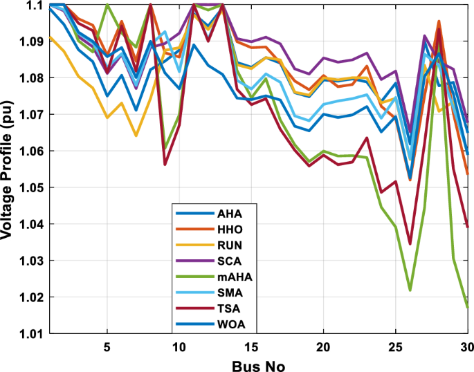
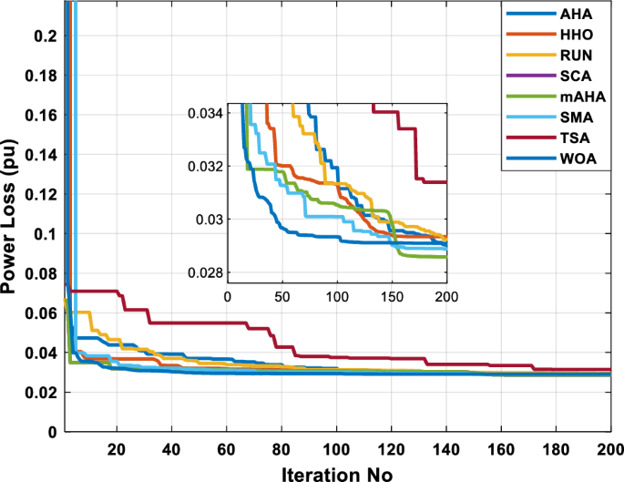
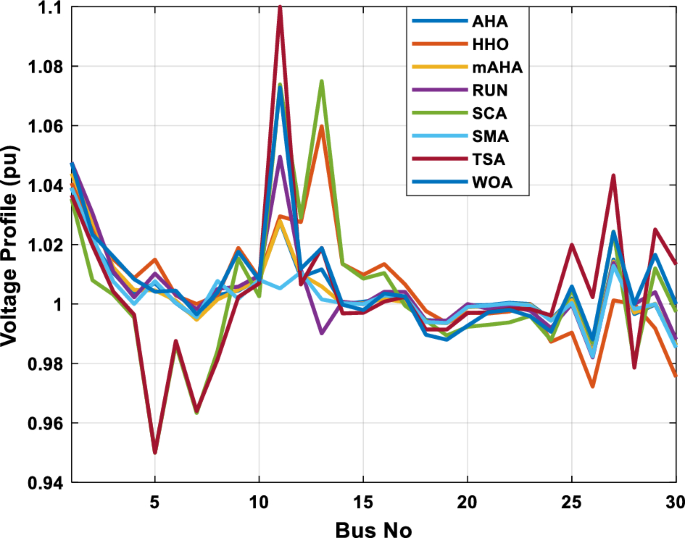
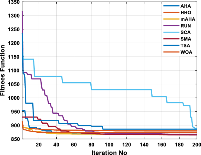
This scenario involves minimizing real power loss as a single objective function. A comparison of the optimum simulation results obtained by the mAHA technique with those obtained by other methods is presented in Table 7. A real power loss of 2.85767 MW was achieved using the mAHA methodology. Alternatively, the other techniques achieved values ranging from 2.90269 to 3.54983 MW. The voltage magnitudes on all buses are within their acceptable ranges as shown in Fig. 8. According to Fig. 9, the mAHA method and other techniques exhibit similar convergence characteristics in terms of minimizing real power loss. From this figure, it is evident that mAHA reaches its optimum solution faster than other methods.
Case 3: minimization of total voltage deviation
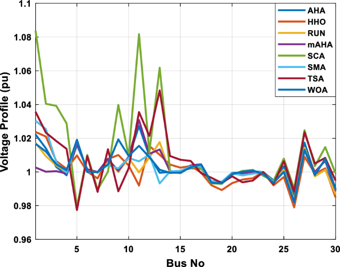
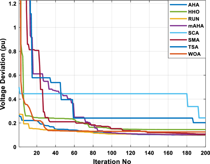
The mAHA technique is employed in this scenario to minimize the total voltage deviation, as discussed in section “Preliminaries“. It is shown in Table 8 that the mAHA technique achieved optimal variables in comparison to the other algorithms. It is evident from the results that mAHA achieved the best and minimum voltage deviation values of 0.09783 pu, outperforming other algorithms such as AHA, HHO, RUN, SCA, SMA, TSA, and WOA, which resulted in values of 0.09841 pu, 0.14498 pu, 0.10214 pu, 0.24245 pu, 0.10708 pu, 0.20299 pu, and 0.12508 pu, respectively. Figure 10 illustrates that mAHA provides the most accurate voltage profile compared to other algorithms. Furthermore, Fig. 11 demonstrates that mAHA’s convergence characteristic outperforms the other compared algorithms.
Case 4: minimization of fuel cost and power losses
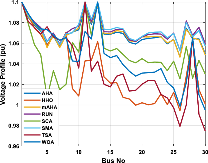
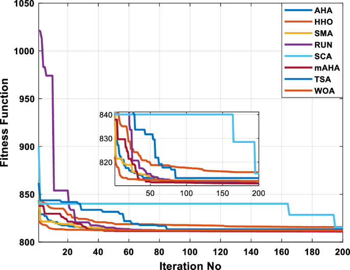
A multi-objective function is considered in this case, which aims to minimize fuel cost and real power loss. A comparison of the most reliable simulation results obtained using the mAHA technique is presented in Table 9. Based on the mAHA technique, an objective function value of 801.8704 was obtained, significantly better than that obtained through other methods, including AHA, HHO, RUN, SCA, SMA, TSA, and WOA. Figure 12 illustrates that all voltage profiles of the buses were within their limits. As shown in Fig. 13, the convergence characteristics of the mAHA technique and the other compared techniques are related to the minimization of the cost function. Therefore, it can be concluded that the mAHA technique performs better than other algorithms when minimizing the cost function.
Case 5: minimization of fuel cost and total voltage deviation
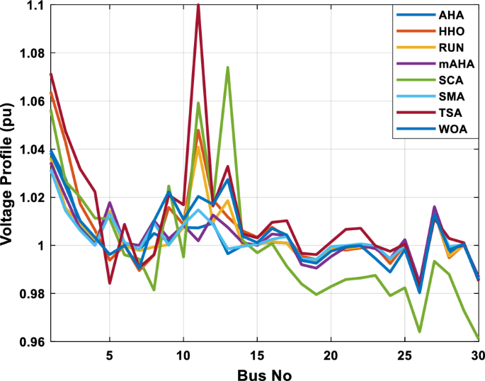
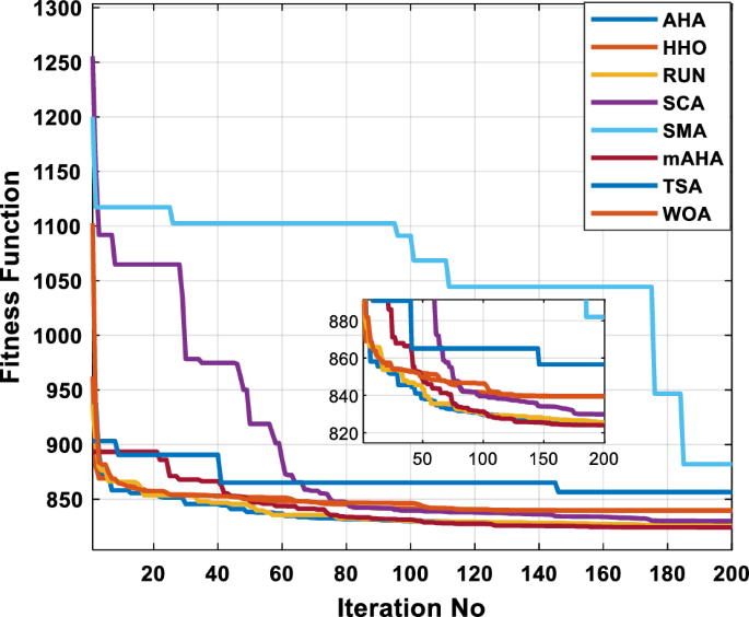
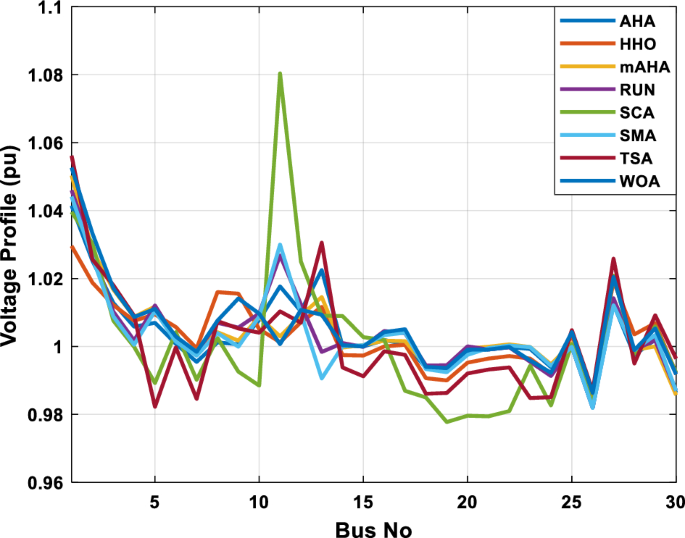
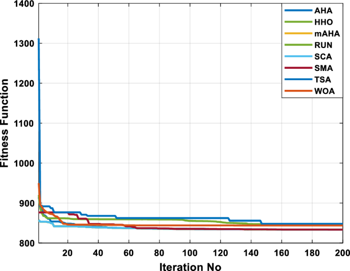
Fuel cost and voltage deviation are minimized in this case, which is considered a multi-objective function. Table 10 compares the most promising simulation results obtained using the mAHA technique with those obtained using other approaches. The mAHA technique yielded an objective function value of 824.0697, which is better than the values obtained using other techniques, such as AHA, HHO, RUN, SCA, SMA, TSA, and WOA, which yielded values of 824.9193, 839.7303, 829.941, 882.0512, 825.729, 856.5994, and 839.5122, respectively. The voltage profiles of all buses were found to be within their limits, as shown in Fig. 14. Based on Fig. 15, the mAHA technique and other comparable techniques are compared in terms of minimizing the cost function. As a result, it can be concluded that the mAHA technique performs better than the other algorithms when minimizing the cost function.
Case 6: minimization of fuel cost and power loss with emission
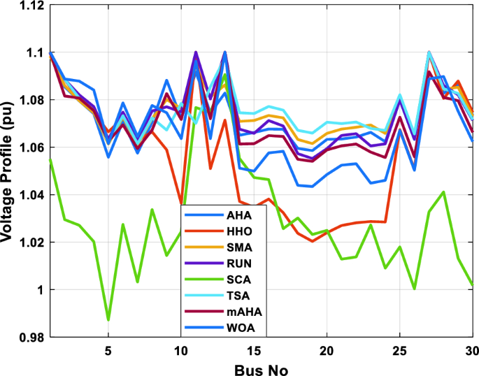
This case involves minimizing fuel costs, losses, and emissions, which are considered multi-objective functions. Table 11 presents simulation results using mAHA and other techniques. The mAHA technique yielded an objective function value of 801.9032, which is better than the values obtained using other techniques such as AHA, HHO, RUN, SCA, SMA, TSA, and WOA, which yielded values of 801.9555, 806.5996, 801.9119, 806.0495, 801.9381, 804.2416, and 802.8859, respectively. The voltage profiles of all buses were found to be within their limits, as shown in Fig. 16. A comparison of mAHA with other compared techniques is shown in Fig. 17 for minimizing the cost function. Based on the comparative results, it can be concluded that the mAHA technique outperforms other algorithms in minimizing the cost function.
Case 7: minimization of multi objective function without emission
Using weighting factors to optimize multiple objective functions simultaneously is recommended, as discussed in section “Application of mAHA: optimal power flow and generation capacity“. This is to ensure that the proposed scheme provides maximum benefits. The mAHA technique was compared to other methodologies in Table 12 for solving the multi-objective OPF issue (fuel cost, real power losses, and total voltage deviation) in the IEEE-30 bus network without considering emissions. The results demonstrate that mAHA is more effective than other techniques in solving multiple objectives OF issues. A total objective function value of 833.5196 achieved by mAHA is better than all other methodologies; AHA, HHO, RUN, SCA, SMA, TSA, and WOA achieved results of 833.594, 847.0193, 835.655, 865.4373, 833.594, 848.0131, and 844.0074 without violating the considered constraints. All compared techniques show voltage profiles within the designated limits, similar to previous cases in Fig. 18. Moreover, as shown in Fig. 19, mAHA’s convergence characteristics are the fastest.
Case 8: minimization of multi-objective function with emission
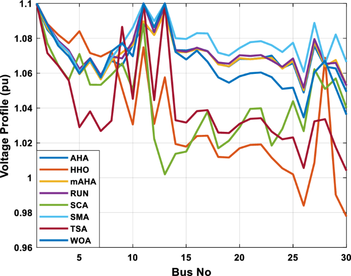
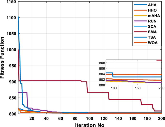
According to Table 13, the mAHA algorithm outperformed the other compared algorithms for solving a multi-objective OPF problem in the IEEE 30-bus testing system. From this table, mAHA offers the best objective function at 864.735 compared to the other techniques. For all algorithms compared in Fig. 20, the voltage profiles indicate that all voltages are within the specified range. As shown in Fig. 21, mAHA has fast convergence, outperforming all other algorithms.
Case 9: optimal allocation for renewable energy sources for minimizing fuel cost
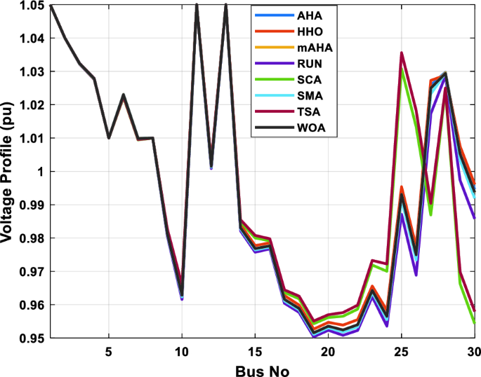
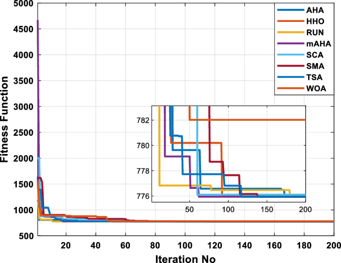
To validate the efficacy of mAHA’s proposed algorithm for integrating renewable sources into the power grid, simulations were carried out on the 30-bus grid to minimize fuel costs. A comparison between the results produced by mAHA and other methodologies can be seen in Table 14. Simulated results show the mAHA technique to be the most efficient, producing the lowest fuel cost at node 27, achieving 775.9469 $/h, outperforming the other techniques. Specifically, the AHA, HHO, RUN, SCA, SMA, TSA, and WOA algorithms achieve results of 775.9475 $/h, 803.5182 $/h, 775.9475 $/h, 776.1083 $/h, 775.9472 $/h, 775.9469 $/h, and 782.0199 $/h, respectively. Additionally, Fig. 22 shows the voltage profile obtained by mAHA, indicating that all bus voltage magnitudes are within acceptable limits. In Fig. 23, mAHA and other compared algorithms are compared regarding their convergence characteristics. It can be seen from the figure that mAHA produces better convergence characteristics than the other algorithms compared. OPF complexity increases as renewable energy sources are integrated into electrical power systems. Based on existing results, this issue has been solved using the mAHA technique.
Case 10: minimization of the fuel cost with the penetration of RES
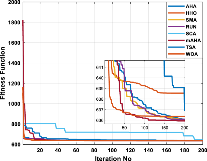
To demonstrate the effectiveness of the proposed mAHA technique, it was compared to recent algorithms for minimizing fuel cost in a single objective OPF issue. The modified IEEE 30-bus system used in case 9 was employed, including RES with optimal allocation. Table 15 presents the results, indicating that mAHA achieved the lowest fuel cost of 636.05 $/h, compared to 636.07 $/h, 638.55 $/h, 636.0871 $/h, 644.9163 $/h, 635.9247 $/h, 636.9435 $/h, and 636.3569 $/h obtained by AHA, HHO, RUN, SCA, SMA, TSA, and WOA, respectively. Furthermore, the proposed mAHA algorithm has superior performance compared to case 1. Using the proposed mAHA algorithm in case 1, fuel cost minimization was achieved at 799.135 $/h, which is higher than the cost minimization achieved by integrating renewable energy sources at 636.05 $/h, adding complexity to the OPF issue. As shown in Fig. 24, all buses have voltage profiles within the limits of their capacity. According to Fig. 25, mAHA and other algorithms are comparable regarding fuel cost convergence. Comparing mAHA with other algorithms, the results show that mAHA exhibits superior convergence characteristics.
Case 11: minimization of the fuel cost simultaneously with the penetration of RES
To demonstrate the effectiveness of the proposed mAHA algorithm, it was compared to other recent algorithms for solving the OPF problem with a single objective function of minimizing fuel cost. The algorithms were tested on a standard IEEE 30-bus system, and Table 16 shows the results. The mAHA algorithm yielded the lowest fuel cost of 285.8574 $/h, outperforming the other algorithms, which achieved fuel costs of 293.04 $/h, 320.71 $/h, 291.51 $/h, 387.2075 $/h, 285.8574 $/h, 296.68 $/h, and 330.0022 $/h for AHA, HHO, RUN, SCA, SMA, TSA, and WOA, respectively.
Moreover, the proposed mAHA algorithm’s superiority is confirmed compared to previous cases (case 1 and case 10). In case 1 and case 10, the mAHA algorithm achieved fuel cost minimization with values of 799.135 $/h and 636.05 $/h, respectively. These values are higher than the fuel cost achieved by the proposed mAHA algorithm, which solved the OPF problem simultaneously with integrating renewable energy sources and achieved fuel cost minimization with a value of 285.8574 $/h.
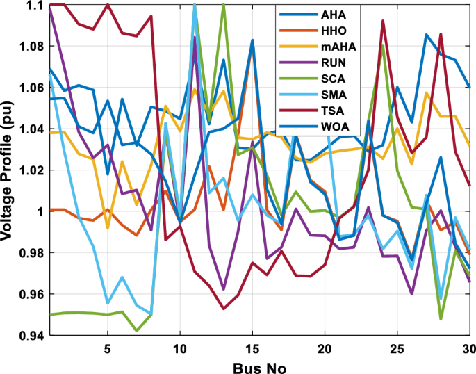
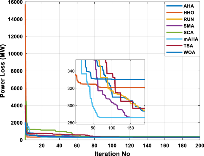
As can be seen in Fig. 26, all buses are within acceptable voltage limits. As shown in Fig. 27, the mAHA algorithm’s convergence characteristics outperform the other compared techniques regarding fuel cost convergence.
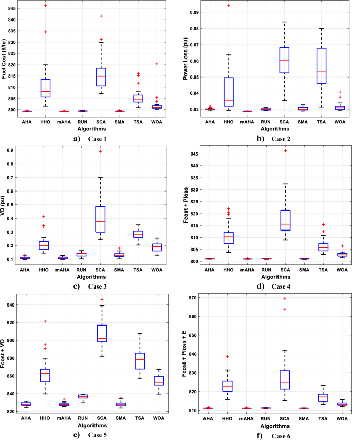
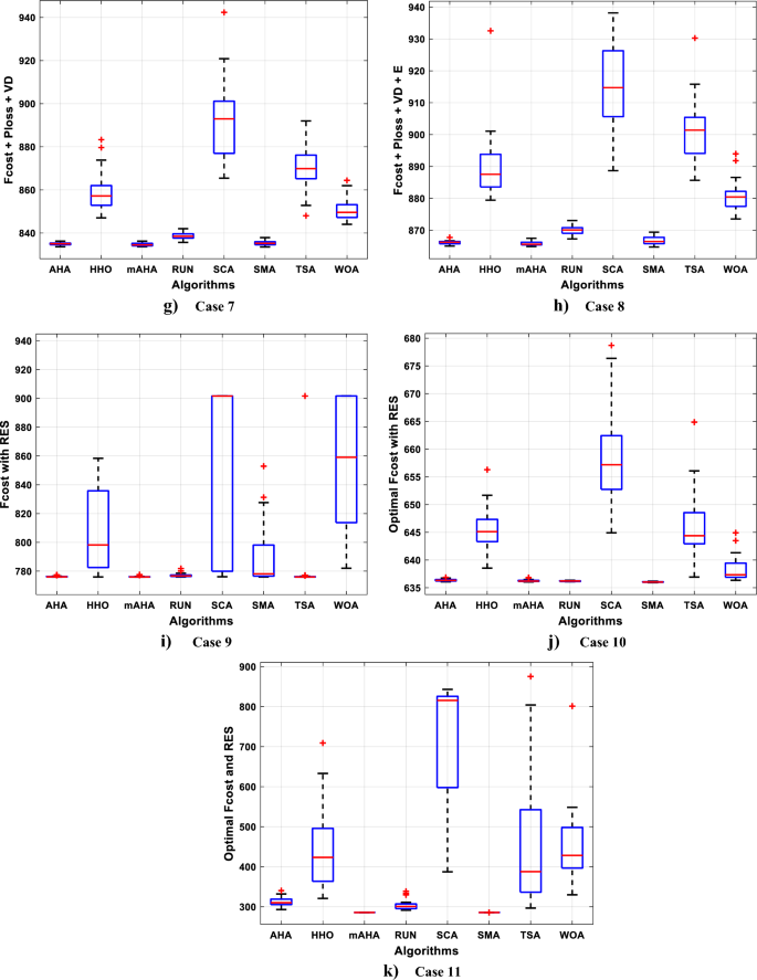
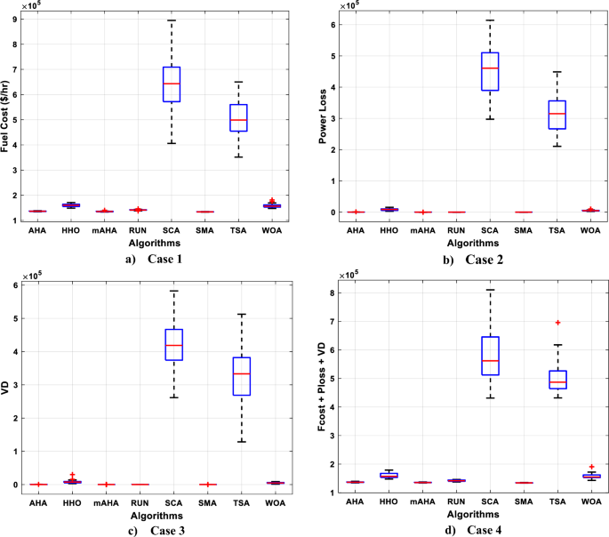
Upon comparing the proposed mAHA’s boxplots with the ones of other methods, it can be observed that these are extremely tight for all cases, with the lowest values shown in Fig. 28.
Also, a Wilcoxon signed rank sum test has been done to compare performance between any two algorithms. This test provides a fair comparison between the proposed mAHA method and the other suggested optimization methods on a specific study case using a signed rank test. Store all fitness values over 30 runs of the objective in a case study for both algorithms. Calculate (p)-value which governs the significance of results in a statistical hypothesis test. The argument against null hypothesis ({H}_{0}) is stronger the smaller the (p)-value. The results obtained using the Wilcoxon signed rank test are offered in Table 17. The column ({H}_{0}) defines whether the null hypothesis is valid or not. If the null hypothesis is valid (i.e. ({H}_{0}) = “1” with a significance level, (alpha ) = 0.05), the performance of the two methods is statistically the same for the study case. The mAHA and AHA perform evenly in cases 1, 3, 4, 5, 6, 7, and 9 while mAHA and SMA are equally in cases 1, 4, and 5. The RUN and TSA performances against AHA are equal in cases 6 and 9 respectively. In the leftover cases, mAHA is found to be superior. Finally, the test findings show that when used to solve the OPF issue in various scenarios, the mAHA outperforms the other optimization approaches, especially for a large number of control variables (large problem) as mentioned in case 11..
IEEE 118-bus grid
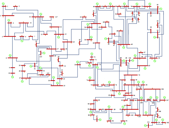
To assess the scalability and effectiveness of the mAHA method for resolving large-scale OPF issues, the IEEE 118-bus standard network is considered. The whole data set for this system is cited in33. Sixty-four load buses, 54 generating units, and 186 branches make up the network. Switchable shunt capacitors are included on twelve buses: 34, 44, 45, 46, 48, 74, 79, 82, 83, 105, 107, and 110. At lines 8–5, 26–25, 30–17, 38–37, 63–59, 64–61, 65–66, 68–69, and 81–80, nine tap-altering transformers have been installed as shown in Figur 29. All buses have voltage magnitude restrictions between [0.95 pu and 1.1 pu]. Each regulating transformer tap’s lowest and maximum values fall within (0.9 1.1) range.
Case 1: fuel cost minimization
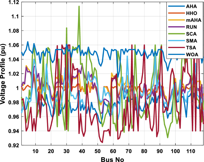
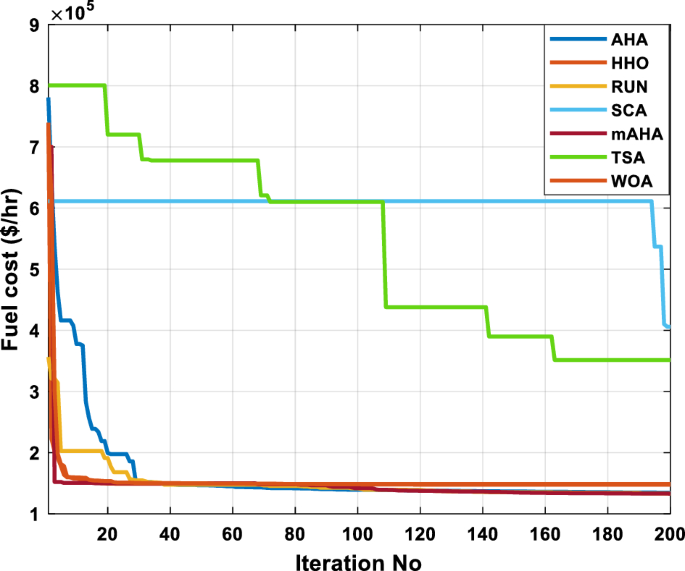
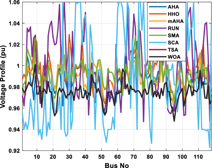
In this part, the OPF issue of the IEEE 118-bus network is solved using the mAHA method without DG. The aim function is cost reduction. Figures 30 and 31 illustrate the voltage profile and cost-saving mAHA algorithm’s convergence graph. The graphic demonstrates the mAHA algorithm’s good convergence characteristic while handling a significant optimization challenge. Table 18 lists the ideal cost reduction values and control variable modifications. The mAHA algorithm found a better solution. The results show how effective the mAHA technique is in quickly converging on the best answer. These findings demonstrate the mAHA algorithm’s effectiveness for resolving significant OPF issues and confirm its scalability.
Case 2: real power losses reduction
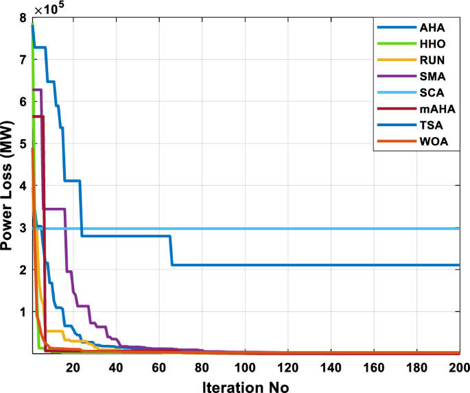
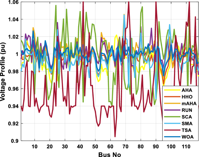
In this situation, active power loss reduction was the objective function. The results of using the mAHA method to arrive at the optimal solution are shown in Table 19. The mAHA algorithm effectively identifies the best control variable values that minimize system losses. As a result, real power losses dramatically dropped to 38.665089 MW when the mAHA algorithm was run without considering DG. Figure 32 illustrates the resilience and accuracy of the mAHA method by showing that the solution found using the mAHA algorithm isn’t violated at any bus, whereas other approaches are violated at multiple system load buses. Figure 33 shows the sharp convergence of real power losses based on the mAHA algorithm compared to other comparative methods. The mAHA method reaches the optimal result after only 20 iterations, demonstrating its rapid convergence. In order to evaluate the algorithm’s efficiency, the estimated real power loss value is compared with that discovered using previously published population-based optimization techniques.
Case 3: voltage deviation minimization
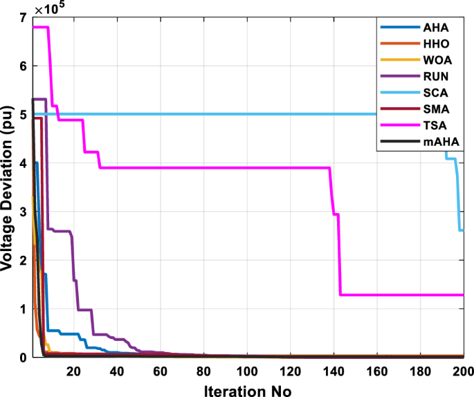
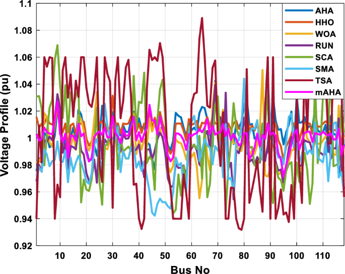
Voltage deviation is chosen as the target function to be improved using the mAHA algorithm to improve the voltage profile. Figure 34 illustrates that, unlike other algorithms, the mAHA algorithm could maintain the allowed voltage constraints. Figure 35 shows the trend of decreasing system voltage deviation. Table 20 presents the findings. The results show that when employing the mAHA method, the voltage deviation index is 0.4264959 pu. Table 18 compares solutions achieved using the mAHA method and other population-based optimization techniques, with the former yielding superior results.
Case 4: lessening of several objective functions devoid of emissions
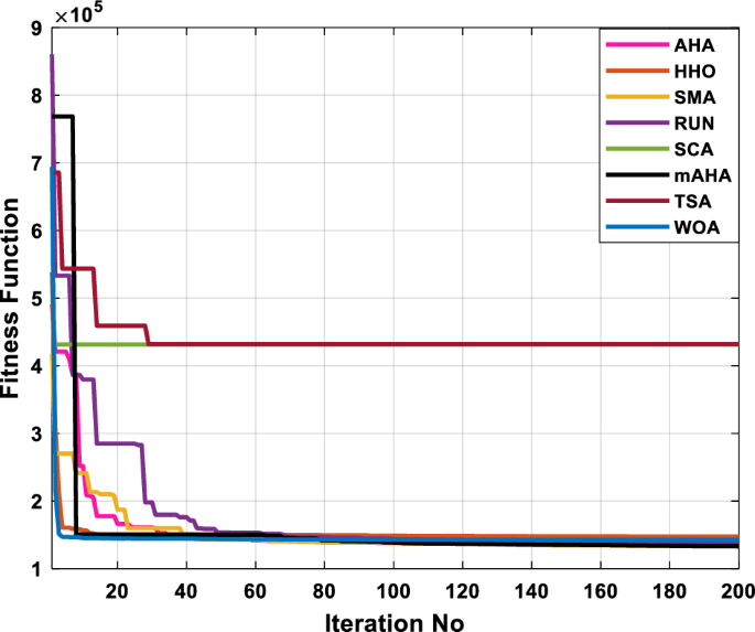
In order to obtain the full benefits of the planned test system, a multi-objective function minimizes fuel operational cost, transmission power loss, and voltage-level deviation is implemented. According to Table 21, the multi-objective OPF issue was tackled by using mAHA in conjunction with other comparative algorithms without considering emissions. Several OF problems can be solved more economically by adopting mAHA than other comparable algorithms. As a result, the total objective function with 133,257.99 $/h based on mAHA technique outperforms all other algorithms with 134,581.11 $/h, 147,663.18 $/h, 137,402.63 $/h, 431,355.38 $/h, 133,921.61 $/h, 431,849.5 $/h and 143,003.58 $/h achieved by AHA, HHO, RUN, SCA, SMA, TSA, and WOA, respectively. All voltage profiles are within the specified limits except for the TSA algorithm, as illustrated in Fig. 36. Furthermore, mAHA still demonstrates quick and smooth convergence characteristics, as seen in Fig. 37. Based on the proposed mAHA algorithm, the boxplots in Fig. 38 display the lowest values for fuel cost, real power losses, and total voltage deviation. As illustrated previously, the boxplots of the proposed mAHA show a high degree of susceptibility to reducing the cost function with the lowest values.
Further, a Wilcoxon signed rank sum test has been executed to compare performance between proposed algorithms. Thirty independent runs are implemented in the test. The selected level of significance is 5%. The (p)-values determined by Wilcoxon’s rank-sum test are shown in Table 22. The ({H}_{0}) values obtained from the test is “0” meaning the null hypothesis is rejected among the optimization algorithms for most cases except case 2 and case 3, where the mAHA and RUN perform equally. In the leftover cases, mAHA is found to be excellent. It can be concluded from the test results that the mAHA is a choice to the other optimization methods when applied to solve the OPF problems under several cases.
Table 23 illustrates comparative results for minimizing the fuel cost (Case 1), power losses (Case 2), voltage deviation (Case 3), and multi-objective function (Case 4) with several other algorithms which are developed SDO, LSDO, PSOIWA, PSOCFA, RGA, BBO, MSA, ABC, CSA, GWO, BSOA, and MJAYA67,68,69. As shown, the proposed mAHA obtain the minimum objective function for all cases among other techniques.
Conclusion
This research develops mAHA, a novel optimizer for dealing with OPF issues, including fuel cost, power loss, voltage profile improvement, and emissions. Additionally, eight approaches for multi-objective and single-objective OPF were presented. The proposed methods were evaluated and confirmed on standard and modified IEEE 30 bus and IEEE 118 bus networks, among others. As a result, the results indicated that the optimum allocation of renewable energy sources (RES) concurrent with the OPF produces better results than if it happens separately. Distributed generation (DG) location and size were added as control variables. As a result, the OPF issue dimension was also expanded. In addressing the OPF optimization issue, mAHA demonstrated excellent performance and efficacy.
Additionally, the most promising results from IEEE Power Networks demonstrate the effectiveness of the suggested approach. Compared to other recent algorithms, the mAHA mitigated the objective functions better in all cases. Based on the comparison results in the case of IEEE 30 bus system, mAHA demonstrated an improvement reduction of single objective functions of 92.874% (Fuel cost), 80.254% (Power losses), and 91.49% (voltage deviation) when compared to AHA, HHO, RUN, SCA, SMA, TSA, WOA, and other published techniques. Furthermore, the comprehensive study of mAHA with the mentioned methodologies has shown that mAHA has met the minimum objective function of 864.735. Additionally, in comparison with the other algorithms, mAHA has the highest fuel cost reduction of 97.451% in the case of minimizing the fuel cost while simultaneously deploying renewable energy sources. As shown in the case of the IEEE 118 bus system, mAHA was superior to other optimizers in finding the global optimum solution of the objective function cases.
Therfore, it is clear that the mAHA outperformed these recent algorithms irrespective of their objective functions, which shows that the mAHA is capable of solving other real-life applications. The OPF problem can be solved by incorporating RES uncertainties in future work for handling as a real problem. Also, the suggested mAHA can be modified or mixed with other metaheuristic algorithms in upcoming work to address other complex optimization problems in dissimilar fields, for example, optimally allocated generation when RES are vague, optimal hybrid RES planning, estimating fuel cell parameters, and modeling photovoltaic systems.
Data availability
The datasets used and analyzed during the current study are available from the corresponding author upon reasonable request.
References
-
Dommel, H. W. & Tinney, W. F. Optimal power flow solutions. IEEE Trans. Power Apparatus Syst. 10, 1866–1876 (1968).
-
Aoki, K. & Kanezashi, M. A modified newton method for optimal power flow using quadratic approximated power flow. IEEE Trans. Power Apparatus Syst. 8, 2119–2125 (1985).
-
Sun, D. I., Ashley, B., Brewer, B., Hughes, A. & Tinney, W. F. Optimal power flow by newton approach. IEEE Trans. Power Apparat. Syst. 10, 2864–2880 (1984).
-
Torres, G. L. & Quintana, V. H. An interior-point method for nonlinear optimal power flow using voltage rectangular coordinates. IEEE Trans. Power Syst. 13(4), 1211–1218 (1998).
-
Houssein, E. H., Oliva, D. & E. C¸ elik, M. M. Emam, R. M. Ghoniem,. Boosted sooty tern optimization algorithm for global optimization and feature selection. Expert Syst. Appl. 213, 119015 (2023).
-
Hashim, F. A., Hussain, K., Houssein, E. H., Mabrouk, M. S. & Al-Atabany, W. Archimedes optimization algorithm: A new metaheuristic algorithm for solving optimization prob- lems. Appl. Intell. 51, 1531–1551 (2021).
-
Eid, A., Kamel, S. & Houssein, E. H. An enhanced equilibrium optimizer for strategic planning of pv-bes units in radial distribution systems considering time-varying demand. Neural Comput. Appl. 34(19), 17145–17173 (2022).
-
Houssein, E. H., Hassan, M. H., Mahdy, M. A. & Kamel, S. Development and application of equilibrium optimizer for optimal power flow calculation of power system. Appl. Intell. 1, 1–22 (2022).
-
Emam, M. M., Houssein, E. H. & Ghoniem, R. M. A modified reptile search algorithm for global optimization and image segmentation: Case study brain mri images. Comput. Biol. Med. 152, 106404 (2023).
-
Houssein, E. H., Abdelkareem, D. A., Emam, M. M., Hameed, M. A. & Younan, M. An efficient image segmentation method for skin cancer imaging using improved golden jackal optimization algorithm. Comput. Biol. Med. 149, 106075 (2022).
-
Houssein, E. H., Emam, M. M. & Ali, A. A. An optimized deep learning architecture for breast cancer diagnosis based on improved marine predators algorithm. Neural Comput. Appl. 34(20), 18015–18033 (2022).
-
Hassan, M. H., Houssein, E. H., Mahdy, M. A. & Kamel, S. An improved manta ray foraging optimizer for cost-effective emission dispatch problems. Eng. Appl. Artif. Intell. 100, 104155 (2021).
-
Mafarja, M. et al. An efficient high-dimensional feature selection approach driven by enhanced multi-strategy grey wolf optimizer for biological data classification. Neural Comput. Appl. 1, 1–27 (2022).
-
Houssein, E. H., Hosney, M. E., Mohamed, W. M., Ali, A. A. & E. M.,. Younis, Fuzzy- based hunger games search algorithm for global optimization and feature selection using medical data. Neural Comput. Appl. 1, 1–25 (2022).
-
Houssein, E. H., Emam, M. M. & Ali, A. A. An efficient multilevel thresholding segmen- tation method for thermography breast cancer imaging based on improved chimp opti- mization algorithm. Expert Syst. Appl. 185, 115651 (2021).
-
Khamees, A. K., Badra, N. & Abdelaziz, A. Y. Optimal power flow methods: A comprehen- sive survey. Int. Electr. Eng. J. (IEEJ) 7(4), 2228–2239 (2016).
-
Kumari, M. S. & Maheswarapu, S. Enhanced genetic algorithm based computation technique for multi-objective optimal power flow solution. Int. J. Electr. Power Energy Syst. 32(6), 736–742 (2010).
-
Khunkitti, S., Siritaratiwat, A., Premrudeepreechacharn, S., Chatthaworn, R. & Watson, N. R. A hybrid da-pso optimization algorithm for multiobjective optimal power flow problems. Energies 11(9), 2270 (2018).
-
Basu, M. Multi-objective optimal power flow with facts devices. Energy Convers. Manage. 52(2), 903–910 (2011).
-
Singh, R. P., Mukherjee, V. & Ghoshal, S. Particle swarm optimization with an aging leader and challengers algorithm for the solution of optimal power flow problem. Appl. Soft Comput. 40, 161–177 (2016).
-
Abdo, M., Kamel, S., Ebeed, M., Juan, Yu. & Jurado, F. Solving non-smooth optimal power flow problems using a developed grey wolf optimizer. Energies 11(7), 1692 (2018).
-
Yong, T., Lasseter, R. & Stochastic optimal power flow: formulation and solution, in,. Power Engineering Society Summer Meeting (Cat. No. 00CH37134), Vol. 1. IEEE 2000, 237–242 (2000).
-
Nowdeh, S. A. et al. Fuzzy multi-objective placement of renewable energy sources in distribution system with objective of loss reduction and reliability improvement using a novel hybrid method. Appl. Soft Comput. 77, 761–779 (2019).
-
Yong, L., Tao, S. & Economic dispatch of power system incorporating wind power plant, in,. International Power Engineering Conference (IPEC 2007). IEEE 2007, 159–162 (2007).
-
Ortega-Vazquez, M. A. & Kirschen, D. S. Assessing the impact of wind power generation on operating costs. IEEE Trans. Smart Grid 1(3), 295–301 (2010).
-
Hetzer, J., David, C. Y. & Bhattarai, K. An economic dispatch model incorporating wind power. IEEE Trans. Energy Convers. 23(2), 603–611 (2008).
-
Alhejji, A., Hussein, M. E. & Kamel, S. Alyami S (2020) Optimal power flow solution with an embedded center-node unified power flow controller using an adaptive grasshopper optimization algorithm. IEEE Access 8, 119020–119037 (2020).
-
Shaheen, A. M., El-Sehiemy, R. A., Alharthi, M. M., Ghoneim, S. S. M. & Ginidi, A. R. Multi-objective jellyfish search optimizer for efficient power system operation based on multi-dimensional OPF framework. Energy 237, 121478 (2021).
-
Alabd, S., Sulaiman, M. H., & Rashid, M. I. M. Optimal power flow solutions for power system operations using moth-flame optimization algorithm. In Proceedings of the 11th National Technical Seminar on Unmanned System Technology 2019: NUSYS’19, pp. 207–219 (Springer, Singapore, 2021).
-
Biswas, P. P., Suganthan, P. & Amaratunga, G. A. Optimal power flow solutions incorpo- rating stochastic wind and solar power. Energy Convers. Manag. 148, 1194–1207 (2017).
-
Khan, I. U. et al. Heuristic algorithm based optimal power flow model incorporating stochastic renewable energy sources. IEEE Access 8, 148622–148643 (2020).
-
Abdollahi, A., Ghadimi, A. A., Miveh, M. R., Mohammadi, F. & Jurado, F. Optimal power flow incorporating facts devices and stochastic wind power generation using krill herd algorithm. Electronics 9(6), 1043 (2020).
-
Sulaiman, M. H. & Mustaffa, Z. Solving optimal power flow problem with stochastic windsolar–small hydro power using barnacles mating optimizer. Control Eng. Pract. 106, 104672 (2021).
-
Li, S., Gong, W., Wang, L., Yan, X. & Hu, C. Optimal power flow by means of improved adaptive differential evolution. Energy 198, 117314 (2020).
-
Shaheen, A. M., El-Sehiemy, R. A., Elattar, E. E. & Abd-Elrazek, A. S. A modified crow search optimizer for solving non-linear OPF problem with emissions. IEEE Access 9, 43107–43120 (2021).
-
Taher, M. A., Kamel, S., Jurado, F. & Ebeed, M. An improved moth-flame optimization algorithm for solving optimal power flow problem. Int. Trans. Electr. Energy Syst. 29(3), e2743 (2019).
-
Majumdar, K., Das, P., Roy, P. K. & Banerjee, S. Solving OPF problems using biogeography based and grey wolf optimization techniques. Int. J. Energy Optim. Eng. (IJEOE) 6(3), 55–77 (2017).
-
Biswas, P. P., Suganthan, P. N., Mallipeddi, R. & Amaratunga, G. A. J. Optimal power flow solutions using differential evolution algorithm integrated with effective constraint handling techniques. Eng. Appl. Artif. Intell. 68, 81–100 (2018).
-
Pulluri, H., Naresh, R. & Sharma, V. A solution network based on stud krill herd algorithm for optimal power flow problems. Soft Comput. 22, 159–176 (2018).
-
Khelifi, A., Bachir, B. & Saliha, C. Optimal power flow problem solution based on hybrid firefly krill herd method. Int. J. Eng. Res. Afr. 44, 213–228 (2019).
-
Al-Kaabi, M. & Al-Bahrani, L. Modified artificial bee colony optimization technique with different objective function of constraints optimal power flow. Int. J. Intell. Eng. Syst. 13(4), 378–388 (2020).
-
Gupta, S. et al. A robust optimization approach for optimal power flow solutions using rao algorithms. Energies 14(17), 5449 (2021).
-
Daqaq, F., Ouassaid, M. & Ellaia, R. A new meta-heuristic programming for multi- objective optimal power flow. Electr. Eng. 103, 1217–1237 (2021).
-
Chia, S. J., Abd Halim, S., Rosli, H. M. & Kamari, N. A. M. Power loss minimization using optimal power flow based on firefly algorithm. Int. J. Adv. Comput. Sci. Appl. 12(9), 1 (2022).
-
Ahmed, M. K., Osman, M. H., Shehata, A. A., Korovkin, N. V. & A solution of optimal power flow problem in power system based on multi objective particle swarm algorithm, in,. IEEE Conference of Russian Young Researchers in Electrical and Electronic Engineering (ElConRus). IEEE 2021, 1349–1353 (2021).
-
Farhat, M., Kamel, S., Atallah, A. M. & Khan, B. Optimal power flow solution based on jellyfish search optimization considering uncertainty of renewable energy sources. IEEE Access 9, 100911–100933 (2021).
-
Ragab, E. L. et al. Quasi-reflection jellyfish optimizer for optimal power flow in electrical power systems. Stud. Inf. Control 31(1), 49–58 (2022).
-
Shaheen, A. et al. Developed Gorilla troops technique for optimal power flow problem in electrical power systems. Mathematics 10(10), 1636 (2022).
-
Ali, M. H., Soliman, A. M. A. & Elsayed, S. K. Optimal power flow using archimedes optimizer algorithm. Int. J. Power Electron. Drive Syst. 13(3), 1390 (2022).
-
Su, H., Niu, Q. & Yang, Z. Optimal power flow using improved cross-entropy method. Energies 16(14), 5466 (2023).
-
Blum, C., Puchinger, J., Raidl, G. R. & Roli, A. Hybrid metaheuristics in combinatorial optimization: A survey. Appl. Soft Comput. 11(6), 4135–4151 (2011).
-
Zhao, W., Wang, L. & Mirjalili, S. Artificial hummingbird algorithm: A new bio-inspired optimizer with its engineering applications. Comput. Methods Appl. Mech. Eng. 388, 114194 (2022).
-
Tizhoosh, H. R. Opposition-based learning: a new scheme for machine intelligence. In: Computational intelligence for modelling, control and automation, 2005 and in- ternational conference on intelligent agents, web technologies and internet commerce, international conference on, Vol. 1, IEEE, pp. 695–701 (2005).
-
Houssein, E. H., Emam, M. M. & Ali, A. A. Improved manta ray foraging optimization for multi-level thresholding using covid-19 ct images. Neural Comput. Appl. 33(24), 16899–16919 (2021).
-
Ahmadianfar, I., Bozorg-Haddad, O. & Chu, X. Gradient-based optimizer: A new meta-heuristic optimization algorithm. Inf. Sci. 540, 131–159 (2020).
-
Zabaiou, T., Dessaint, L.-A. & Kamwa, I. Preventive control approach for voltage stability improvement using voltage stability constrained optimal power flow based on static line voltage stability indices. IET Gen. Transm. Distrib. 8(5), 924–934 (2014).
-
A. W. Mohamed, A. A. Hadi, A. K. Mohamed, N. H. Awad, Evaluating the performance of adaptive gainingsharing knowledge based algorithm on cec 2020 benchmark problems, in: 2020 IEEE Congress on Evolutionary Computation (CEC), IEEE, 2020, pp. 1–8.
-
Mirjalili, S. & Lewis, A. The whale optimization algorithm. Adv. Eng. Softw. 95, 51–67 (2016).
-
Mirjalili, S. Sca: A sine cosine algorithm for solving optimization problems. Knowl. Based Syst. 96, 120–133 (2016).
-
Kaur, S., Awasthi, L. K., Sangal, A. & Dhiman, G. Tunicate swarm algorithm: A new bio-inspired based metaheuristic paradigm for global optimization. Eng. Appl. Artif. Intell. 90, 103541 (2020).
-
Li, S., Chen, H., Wang, M., Heidari, A. A. & Mirjalili, S. Slime mould algorithm: A new method for stochastic optimization. Future Gen. Comput. Syst. 111, 300–323 (2020).
-
Heidari, A. A. et al. Harris hawks op- timization: Algorithm and applications. Future Gen. Comput. Syst. 97, 849–872 (2019).
-
Ahmadianfar, I., Heidari, A. A., Gandomi, A. H., Chu, X. & Chen, H. Run beyond the metaphor: An efficient optimization algorithm based on runge kutta method. Expert Syst. Appl. 181, 115079 (2021).
-
Awad, N., Ali, M., Liang, J., Qu, B., & Suganthan, P. Problem definitions and evaluation cri- teria for the cec 2017 special session and competition on single objective real-parameter numerical optimization, Tech. Rep.
-
Williamson, D. F., Parker, R. A. & Kendrick, J. S. The box plot: A simple visual method to interpret data. Ann. Int. Med. 110(11), 916–921 (1989).
-
Abido, M. A. Optimal power flow using particle swarm optimization. Int. J. Electr. Power Energy Syst. 24(7), 563–571 (2002).
-
Daqaq, F., Hassan, M. H., Kamel, S. & Hussien, A. G. A leader supply-demand-based optimization for large scale optimal power flow problem considering renewable energy generations. Sci. Rep. 13(1), 14591 (2023).
-
Yadav, V., & Ghoshal, S. P. Optimal power flow for IEEE 30 and 118-bus systems using Monarch Butterfly optimization. In 2018 Technologies for Smart-City Energy Security and Power (ICSESP), pp. 1–6 (IEEE, 2018).
-
Elattar, E. E. & ElSayed, S. K. Modified JAYA algorithm for optimal power flow incorporating renewable energy sources considering the cost, emission, power loss and voltage profile improvement. Energy 178, 598–609 (2019).
Funding
Open access funding provided by The Science, Technology & Innovation Funding Authority (STDF) in cooperation with The Egyptian Knowledge Bank (EKB).
Author information
Authors and Affiliations
Contributions
M.M.E.: software, methodology, data curation, conceptualization, formal analysis, resources, visualization, validation, writing—review and editing. E.H.H.: supervision, methodology, formal analysis, visualization, writing—review and editing. M.A.T.: data curation, conceptualization, formal analysis, resources, visualization, validation, writing—review and editing. M.M.Z.: data curation, conceptualization, formal analysis, resources, visualization, validation, writing—review and editing. M.H.A.: software, methodology, data curation, conceptualization, formal analysis, resources, visualization, validation, writing—review and editing. All authors read and approved the final paper.
Corresponding author
Ethics declarations
Competing interests
The authors declare no competing interests.
Additional information
Publisher’s note
Springer Nature remains neutral with regard to jurisdictional claims in published maps and institutional affiliations.
Rights and permissions
Open Access This article is licensed under a Creative Commons Attribution 4.0 International License, which permits use, sharing, adaptation, distribution and reproduction in any medium or format, as long as you give appropriate credit to the original author(s) and the source, provide a link to the Creative Commons licence, and indicate if changes were made. The images or other third party material in this article are included in the article’s Creative Commons licence, unless indicated otherwise in a credit line to the material. If material is not included in the article’s Creative Commons licence and your intended use is not permitted by statutory regulation or exceeds the permitted use, you will need to obtain permission directly from the copyright holder. To view a copy of this licence, visit http://creativecommons.org/licenses/by/4.0/.
About this article
Cite this article
Emam, M.M., Houssein, E.H., Tolba, M.A. et al. Application of modified artificial hummingbird algorithm in optimal power flow and generation capacity in power networks considering renewable energy sources.
Sci Rep 13, 21446 (2023). https://doi.org/10.1038/s41598-023-48479-6
-
Received:
-
Accepted:
-
Published:
-
DOI: https://doi.org/10.1038/s41598-023-48479-6
Comments
By submitting a comment you agree to abide by our Terms and Community Guidelines. If you find something abusive or that does not comply with our terms or guidelines please flag it as inappropriate.
This post was originally published on this site be sure to check out more of their content


